Building Prusa Mendel i2.
Contents
- Historical Notes
- What is Reprap Prusa Mendel i2?
- BOM, Bill of Materials.
- Frame.
- Installing motors.
- Extruder.
- Installing X-axe and extruder.
- Installing Y-axe and print bed.
- Electronic components.
- The look.
- Software.
- Test print.
- Conclusion.
Historical Notes:
How it all began? First, I wanted to replace a small part in a model. A trak segment. I used epoxide, and after I got another ugly failure, that haven't had a single straight line, I thought "if only I had a 3d printer!" Then, just out of curiocity, I looked up models and prices in the Internet.
I expected prices to start at 50 K... Well... There are printers that cost that much. However, the "entry level" prices began at 200. Dollars, not thousands. And I suddenly realized, that I want one of those toys for myself.
...
What is Reprap Prusa Mendel i2?
Two words about the device itself. Reprap is a name of a family of low-cost 3d printers that you can build at home using freely available tools and materials. Mendel was a plant biologist, predecessor of the modern genetics. "Our printers will evolve, improving with each generation", something like that. Surprisingly, it worked. Prusa (if you want to pronounce it correctly, it is "Prusha") is a Chech engineer contributed to that particular model. As for i2, it stands for "iteration 2", a second version, improved over the first one. Generally speaking, it is almost perfect.
Reprap is an opensource project, you can create one, or modify its specs, if you want.
Repraps use plastic filament, the only thing you will have to purchase, as there are high requirements to quality. Not that it was expansive. Besides, enthusiasts do print with anything, including chocolate or the fishing line.
BOM, Bill of Materials.
Where and what to buy?
An unpleasant side effect of the opensource development model is an unimaginabe mess with documentation. You can find few schematics for Prusa i2, and all are "correct". To help, here is the link to the description and pictures related to the version I am going to build: click
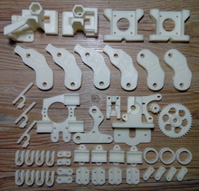
Plastic parts. They can be printed on a 3d printer ("rep" in "Reprap" stands for "replication"), or if you don't have one... There are cases, when people used wood, for example. But generally, you can buy them online. Here is an archive with STL files.
Electronical amd non-plastic components. They are all available online, or in local stores. They are all relatively cheap.
How to order components. Two sources: aliexpress.com and eBay, I prefer aliexpress as their logistics is a bit more reliable. Both sources have surprisingly low prices. Except, sometimes, a delivery of $1 part cost $50... but there are always other, more adequate sellers.
As for bolts and nuts, look in the local construction store.
A fair warning.
Being quite reliable, Repraps are nevertheless simple as a brick, particularly in the safety systems, that are simply not there. If it catches the fire, it will burn, with or without your appartment, depending on your luck. Frankly, there are tens, maybe hundreds thousands of Repraps, and I never heard about such accidents, but... But enthusiasts found combination of conditions for it to combust, so it is THEORETICALLY possible. You can find more info on forums, a good starting point is reprap.org.
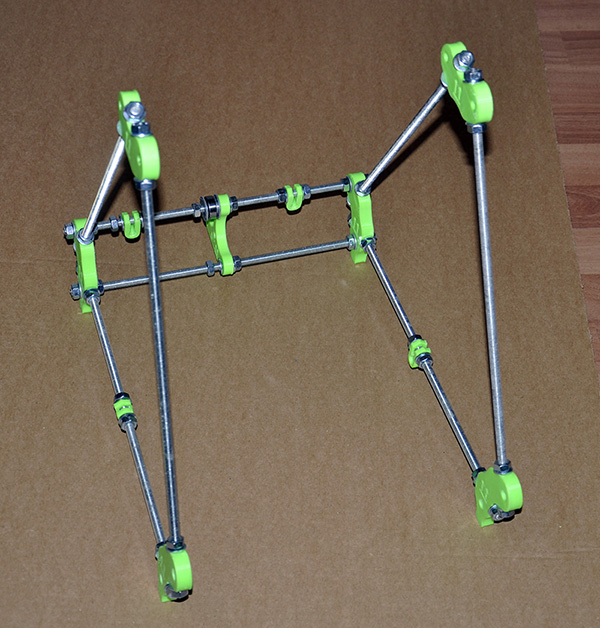
Frame.

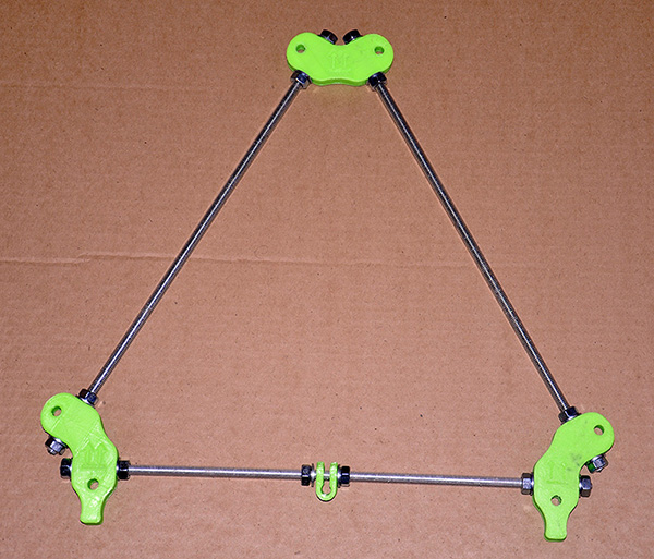
Build two sides. The length of all three sides in a resulting triangle should be equal.
An important note about plastic parts. Different printers are set to use different extrusion temperature, for example, when using ABS plastic, it can be anywhere between 210 and 240 degrees. Also, plastic filament differs depending on the provider, water in it and so on. As the result, plastic shrinks differently when cooling down to the room temperature. Plus, when the spec says "8 mm hole", it corresponds to the 8 mm hole in a 3d model, printer prints an 8 mm hole, and then it shrinks, and suddenly it is 7.5 mm, and you have to use files or drill to mak it up to specs. I use a drilling machine, a cheap version of what dentists use. Bought on Alibaba, by the way.
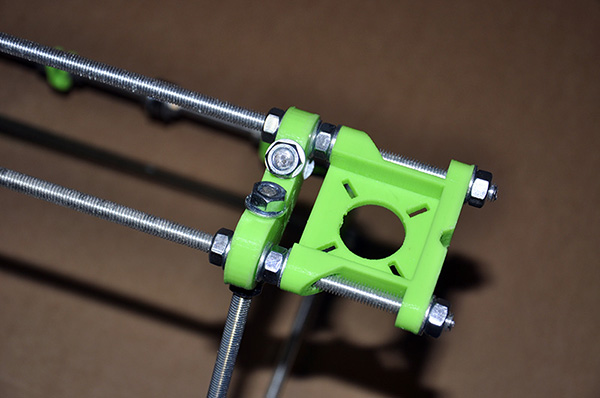
As you can see on the photo, to fix details we use nuts and washers. Make it firm, but do not apply excessional force, with sufficient amount of enthusiasm, you can break the plastic.
Prusa i2 has two rods on front and two on back side. It makes the frame stronger, besides, you can attach motors, power supply unit etc.

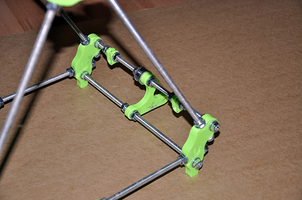
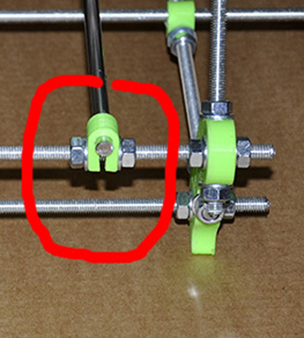
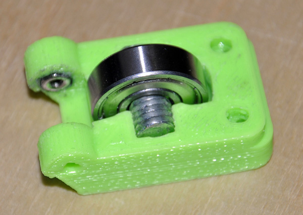
Note the way bearing is installed. Its central part is being fixed by washers, that are small enough in order to NOT touch the outer part. For the belt (we are going to use the belt here) to be held in place, we add two large washers on the sides, small washers providing extra space, so that large ones do not touch the bearing.
There are two approaches. The first one was decribed above, while in the second one, you install bearing guides on top of a washer. I saw both approaches implemented, and both work just fine. Nevertheless, I am going use bearing guides in this particular build, in order to forrlow the spec.
Back and two sides together. I am going to call "back" the side where Y-motor will be installed.
Same junction, close up. As long as all frame isn't assembled, there is no need to tighten nuts.
Similarly, we are assembling the front side.Instead of the motor, we have a bearing here.
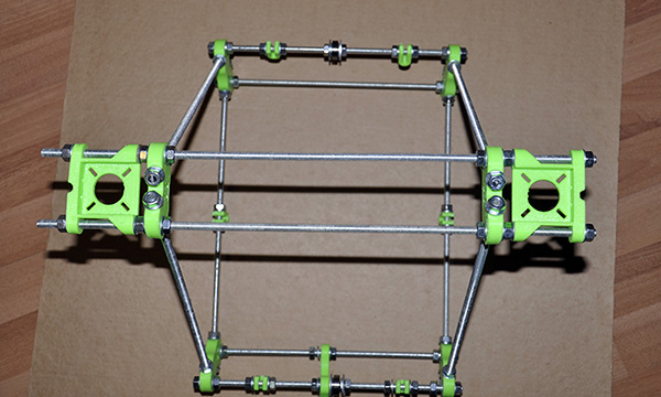
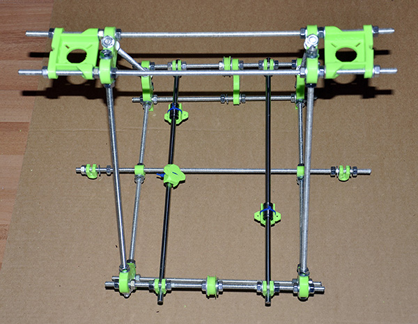
Front and back parts, assembled.
Same, different perspective.
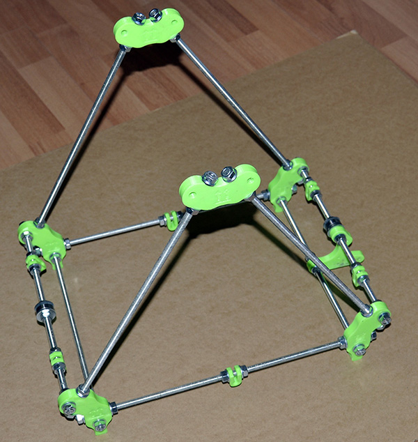
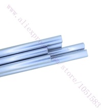
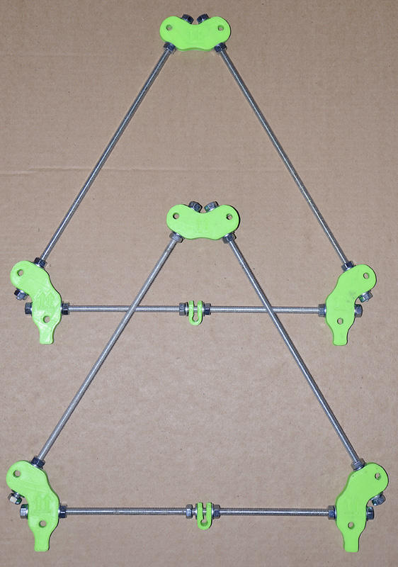
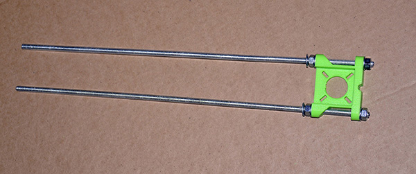
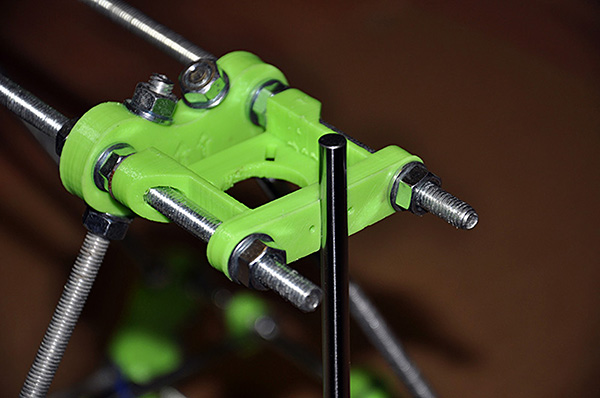
At the top of a frame we use two 8mm rods. They will go through the frame wertex. A rectangular detail on a photo is a Z-motor mount. Reprap has 2 Z-motors, connected in parallel, responsible for vertical movements of an extruder.
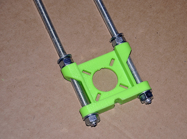
Depending on the degree of shrinking of plastic details you will have to apply a lot of force... or use files to make holes wider.

Notice the nut installed between two plastic details. As you can guess, it does nothing, that the outer nut can not do. The reason we use that nut is to move the motor to the side, because we need to keep our frame sides vertical... The nut is one of the ways to add extra space, if necessary. Accordingly, you can see printers with no nut, one nut or even two nuts - it is notmal.
Also note the ends of rods on the top side of a frame. When we finish the frame, we are going to use ruler to make it proper... We will be looking for sides being vertical, triangles having equal sides and front and back sides equal.
Summarizing (I am still talking about an extra nut), we want to make sure that as extruder moves up and down, the Z-motor and a threaded rod moving the extruder remained co-axial, instead of wobbling.
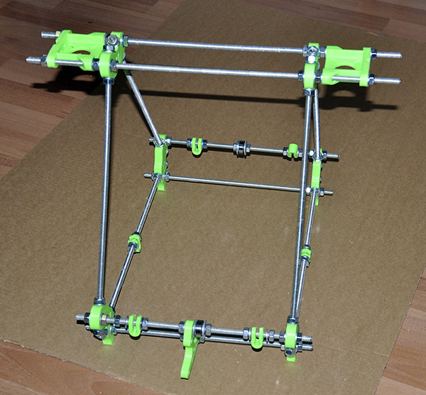
Add an extra rod at the bottom. It is for frame's strength as well as a support for Z-axe.
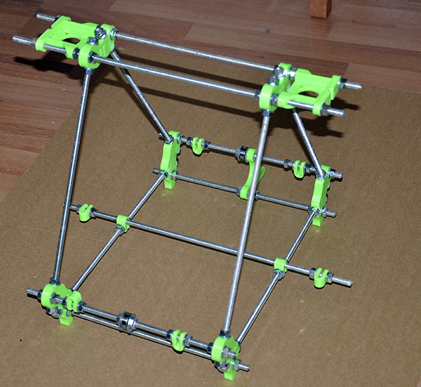
These details can easily be broken, do not apply more strength than necessary.
From a different perspective.
Y-axe.
Our printer has 3 axes. First, the extruder moves left-right, this is X-axe. Second, the print bed moves forward-backwards, this is an Y axe. Finally, as we print, an extruder moves gradually up, this is a Z-axe.
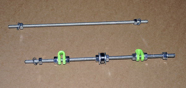
By the way, here are the bearing guides, as we are going to use them after all.
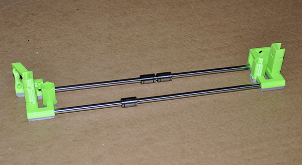
Now take a close look at the following picture. It is wrong.

Here I have made a mistake, and that mistake passed unnoticed for quite some time. As the result, on a few photos, you will see smooth rods guiding Y-axe, going UNDER the threader rod.
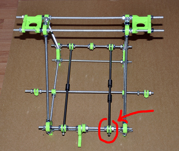
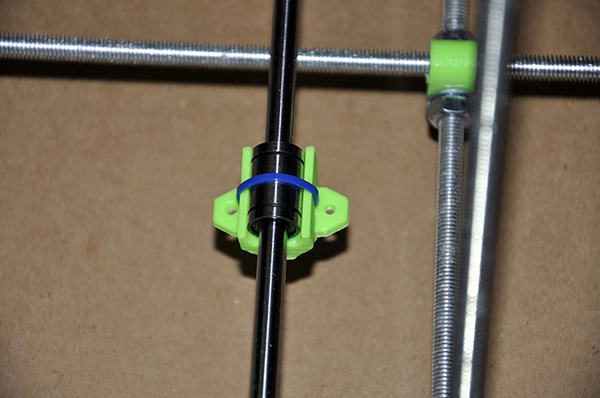
This is a mistake, here is what it should look like:
So, looking at next few photos, keep in mind that at some point down the road I cursed and re-installed these rods properly.
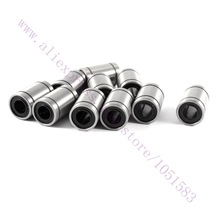
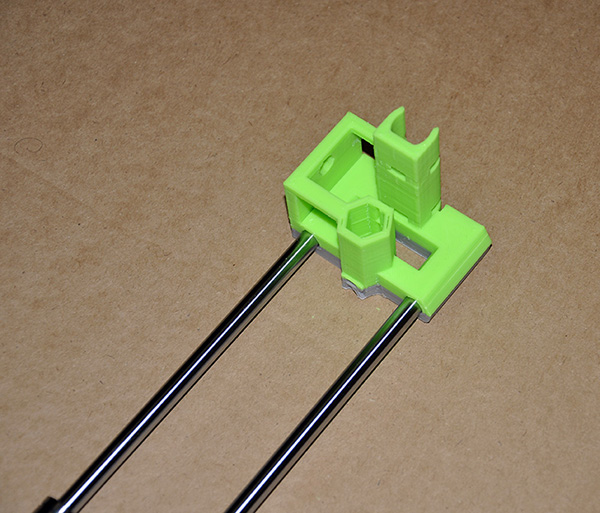
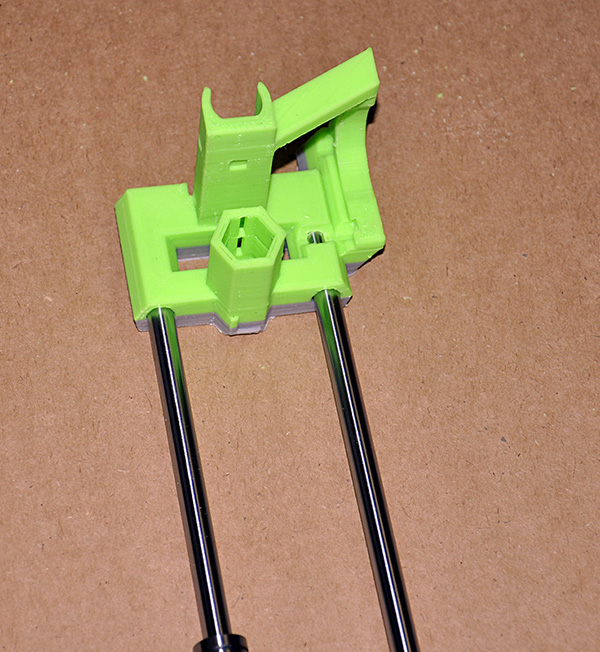
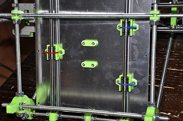
On the picture above, you can see linear bearings sliding by the smooth rods.
We are going to attach plastic details to these rods, and these details, to the bottom side of a printing bed, accordingly.
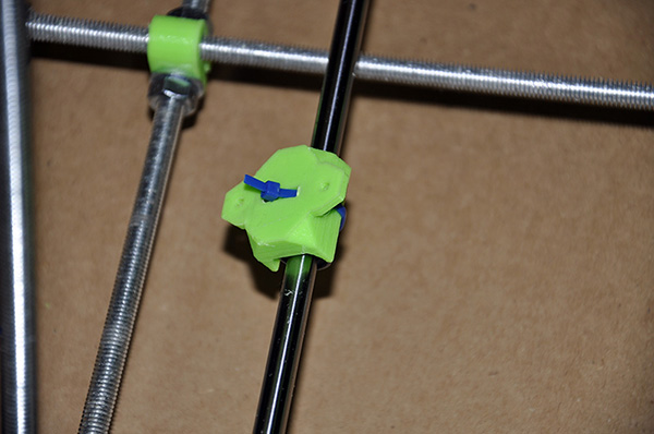
The result:
X-axe.
Depending on the "sub-version" of the printer plastic details set, the platform sliding by the X-axe can have 3 or 4 linear bearings. Axes themselves are squezeed into the plastic details, so make sure right is right and left is left, before applying force
Right and left sides are different, one carries the motor, the other has a bearing to guide the belt.

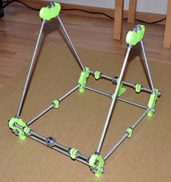
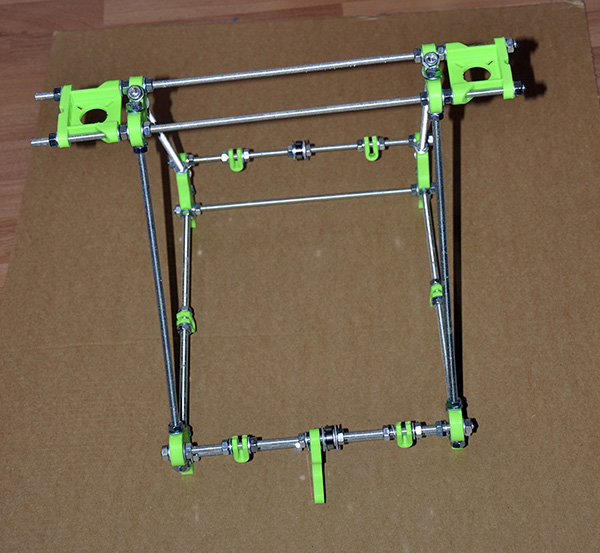
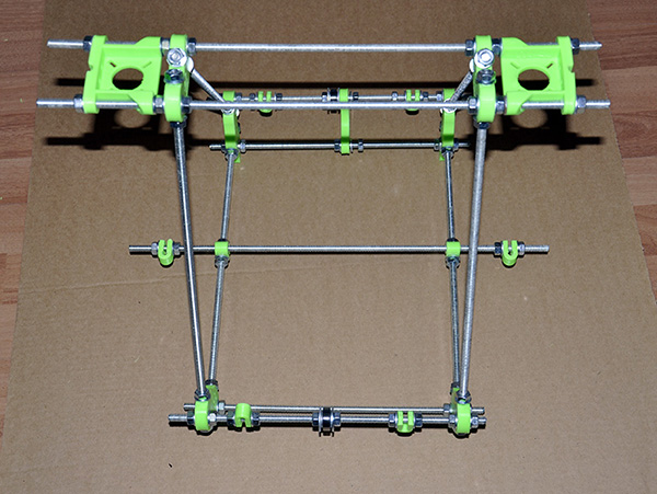
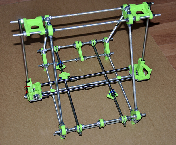
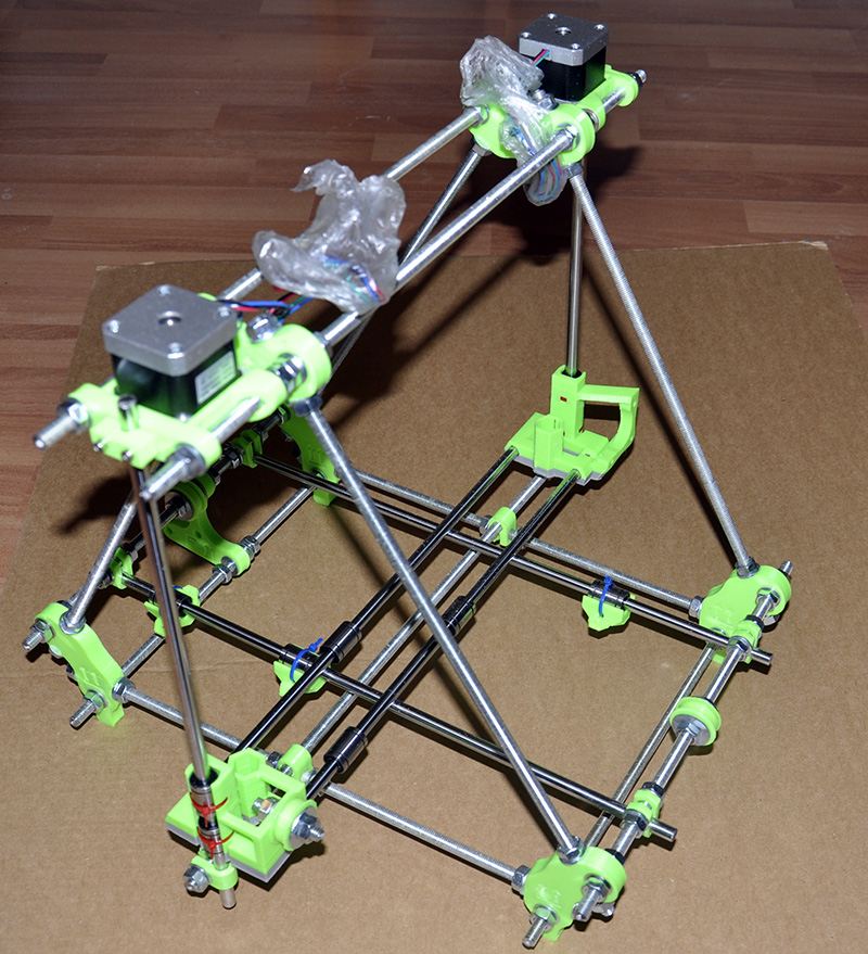
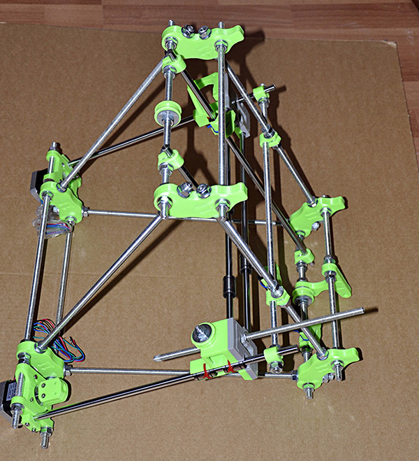
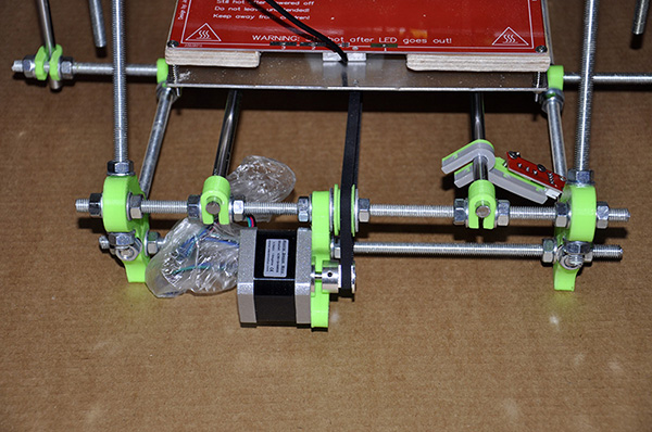
Fully assembled construct, except smooth rods on Y axe are still up side down. We also have elements of a Z-axe here, because X-axe is attached to it:
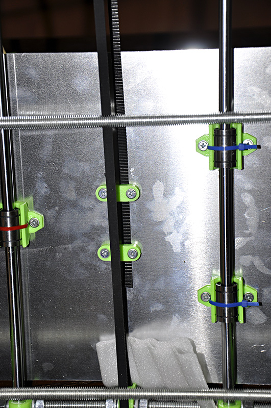
Z-axe.
As you can see on a photo, there are two bearings on the rod. Using only one would yeld more "wobbling", while we want to keep out Z-movement as vertical as possible, otherwise we'll end up having interesting artifacts(ghosting).
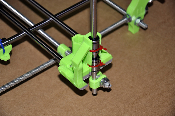
Also it is important to keep track of which side is left and which ir right. Well... Not that it is fatal, we can use software settings later to fix things, but... it is better to keep track of sides.
As always, bearings are attached to plastic using tighteners.
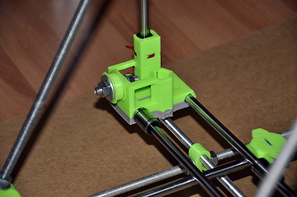
Smooth rod guides the vertical motion. It passes outside the Z-motor holder.

On this photo you can see holes used to bolt in the detail that will hold the smoomh rod in place.
Installing motors.
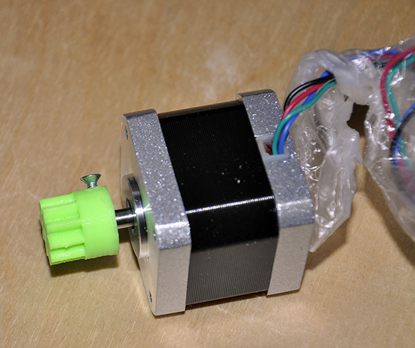
We are going to use five (identical) stepper motors NEMA-17. I believe this is an ideal solition, however, there are nuances. First, NEMA-17 is not a brand, but rather a type of the motor, so anybody can make it. It means - as with any electronic component - that there is a chance to purchase cheap low quality junk. You can read customer reviews for a particular seller, but there still is the risk.

Second, motors differ by the torque. You can find all kind of details on forums, briefly: what you need is maximum force with minimum heating. The longer the motor body is, the more torque it can produce, but I advice against becoming fanatical here. Let me make your life easier: my motors are 4 cm long. Five is ok. 3 is less than you need. If you have no choice, you will probably be able to reduce (in the software settings) the speed ofprint to get away with weak motors, but why would you do it?
If you think that measuring motor power in centimeters are not scientific enough, look for the current. 1.7 amperes is ok. 0.5 - insufficient. On the next photo the motor has the extruder gear on it.
It is a common belief that motors vibrate and that vibration should be suppressed in order not to pass it to the printing hear. In theory, this can lead to ghosting, in reality, it is not the most common reason for the ghosting, and not the most frequent one. But yes, it can reduce precision of the printer. Therefore, we need to ann something soft between the motor and the motor holder, in my case a plastic foam is used. Z-motor does not spin that fast, so it is thin; I am going to use thicker ones for X and Y motors.
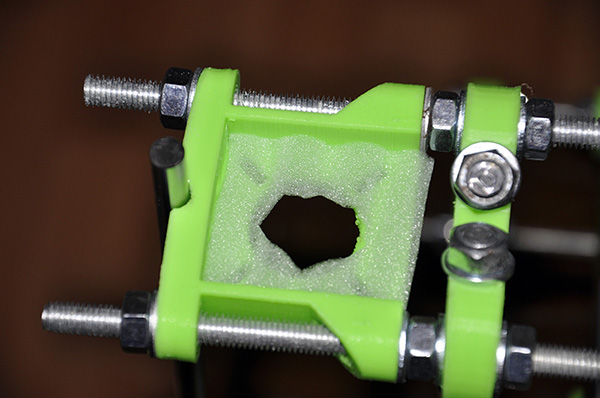
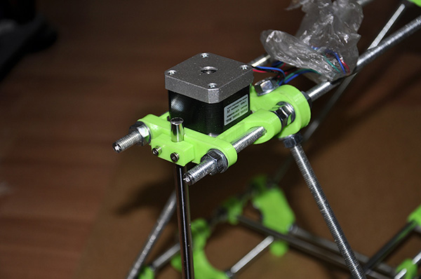
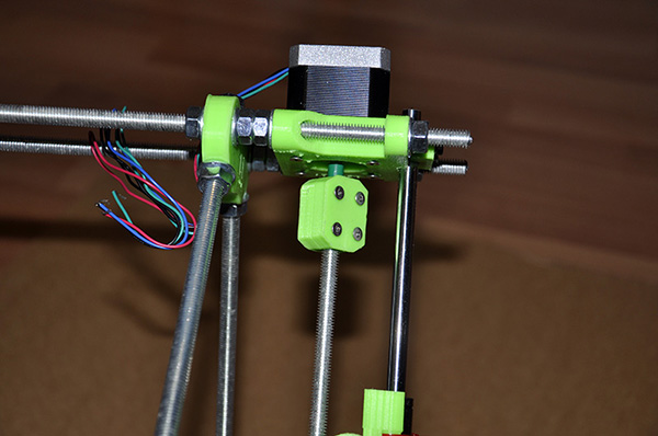
Now we can insqtall Z-motors. Note that it is up to you to decide in which direction wires will go, it is not part of the spec. My choice is great, but if you have your reasons, feel free to go another way.

Generally, the idea of Reprap wiring is to put wires closer to frame and then to wrap them together to produce something neat. So I am placing wires closer to the frame from the very beginning.
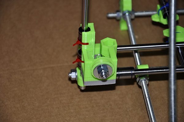
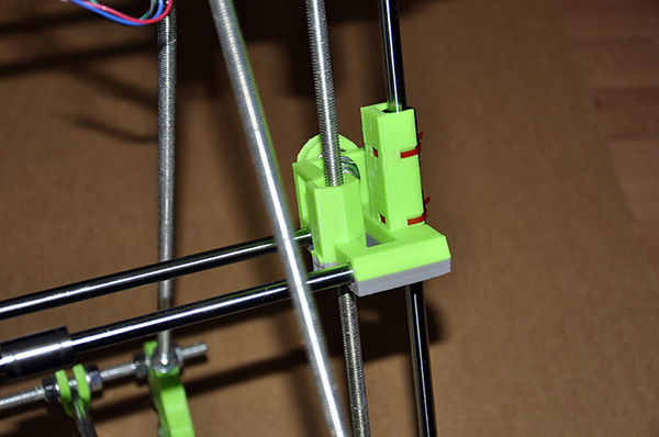
Note how the vertical smooth rod is fixed by the plastic detail with two bolts. The operation is simple, but it is important for the rod to be vertical. If not - we move nuts on the top side of a frame, together with Z-motor holder.
On this photo you can see that the smooth rod does not touch the surfase of the table. There is an opinion that using it as an extra support can lead to parazitic vibrations.

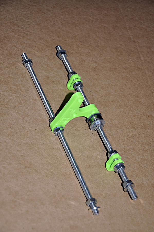
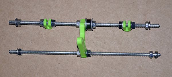
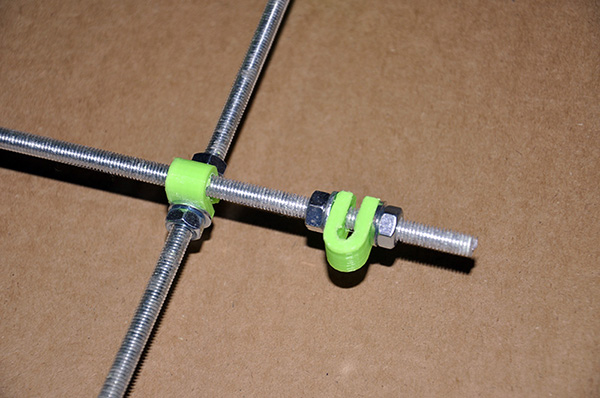
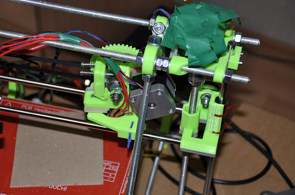
Z-motors turn the threaded rod (М8, eight mm in diameter), which allows us to move the X-axe up an down, together with the extruder. The photo shows the process of installing the rod. First, put the nut on the very tip of a rod. Then insert the second nut into the hole in the detail. The idea is to fix the detail between two nuts, one on top, one on the bottom. Screw in the rod carefully: we need to have as little free space between nuts as possible. Two mm is ok, but no more.
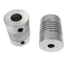
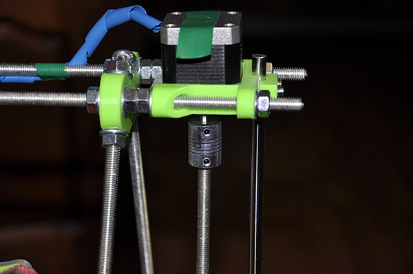
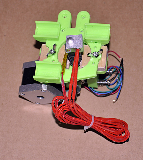
Install both rods. The green octogonal detail on the motor's axe is supposed to hold together the motor and the threaded rod. Well... Let me tell you the truth: it is a bad solution. Plastic is just not up to the task. It affects both precision and what is worse, you never know when it collapses. So - see below - I bought aluminium couplings. They are very cheap, and degree of magnitude more reliable.

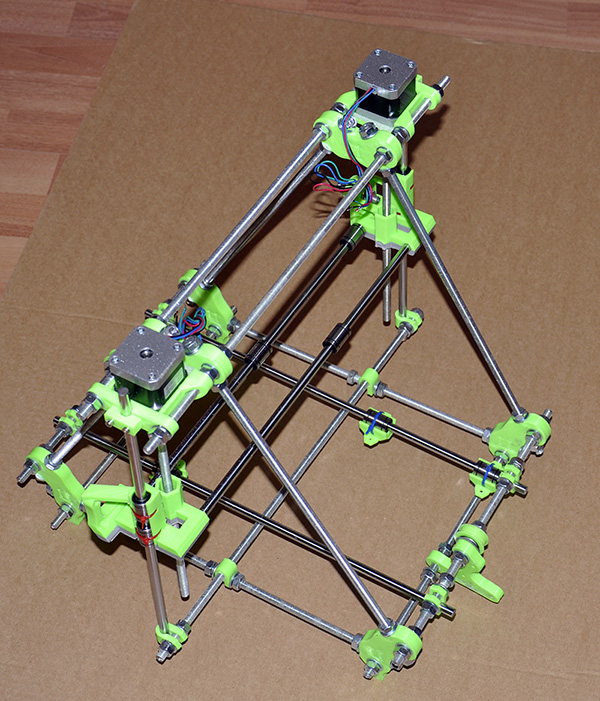
Ok, X-axe is installed, and of course, if should be horizontal. You can level it by turning individual Z-motor by hand.
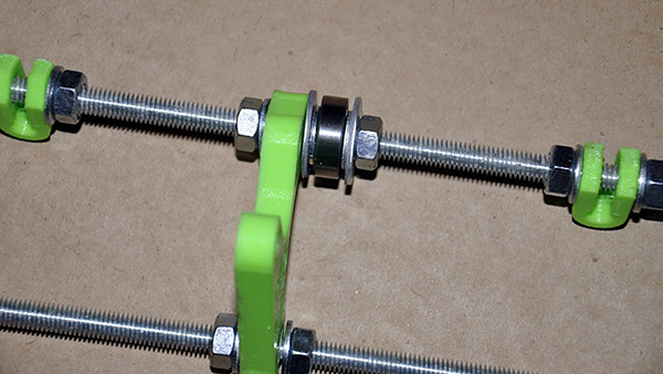
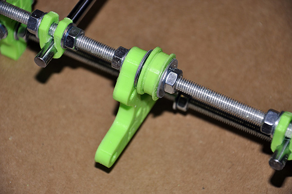
The plastic coupling up close. Let me repeat again: do not save here, get a metal one.
X-axe, assembled and installed.
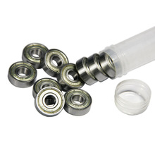
Let's talk about couplings. After my plastic ones collapsed and X-axe felt (luckily, the hotbed was not installed yet, so no damage), I bought aluminium ones on eBay. The spiral cut is required, because our printer is not a precision tool, and even if it was, if would seaseto be after the first time you lift if by the frame. Anyway, we need the motor's axe and the smooth rod of Z-axe to be co-axial, or it simply will not work. Ynless we connect them via the spring, which will absorb slight imperfections, allowing the thing to rotate smoothly.
It is also worth mentioning that I have made a mistake ordering. There are two tyes of couplings for Repraps, depending on the diameter of the threaded rods we use: 5 mm and 8 mm. If the rod is 8 mm, as in the case of i2, the coupling should be marked as 5x8mm, 5 mm for the motor, 8 mm for the rod. However, there are different models, some using 5mm rods, and I bought 5x5mm couplngs. Not a big deal, I have a cutter, a wonderfull little device, a cheap replica of what your dentist uses. On a photo you can see a threaded rod improved. It is not quite clear from the picture, but one side of the masterpiece is flat for the grub screw to hold against it.

Extruder.
Assembling the extruder.
In our printer, we are going to use Wade's extruder, a classical solution, maybe not as compact as one of direct extruders, but less demanding in terms of the power characteristics of the motor. Of course, if you don't like it, you can alwys print something else, but... So far I like it and even when compared to a direct extruder: it is as good as other models.
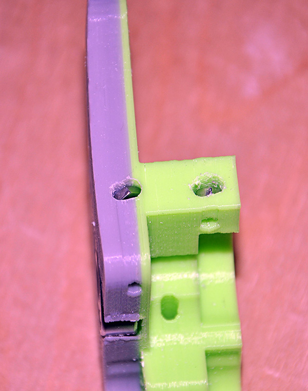
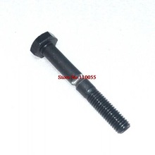
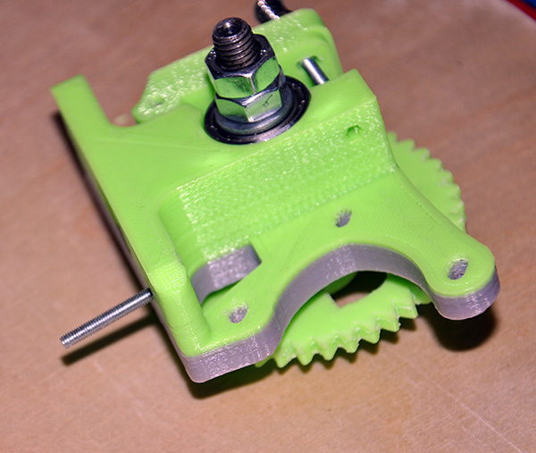
We are going to begin with the plastic part that pushes the filament to the hobbed bolt. As you can see from the photo, the short rod with the bearing on it is simply pressed in (with pliers) its place. According to specs, it should be a smooth one, I personally prefer a threader rod, it holds better.
Also, the nut is pressed into the plastic: heated with the soldering iron, pressed with pliers. As any engineer will tell you, this is a bad solution. So far I am going to follow the spec, but later on I am going to remove the nut and move it to the outer side of the detail to assure that it is not going to fall off.
The assembling itself is simple, but we have to mae sure extra plastic is removed, so the bearing can rotate.
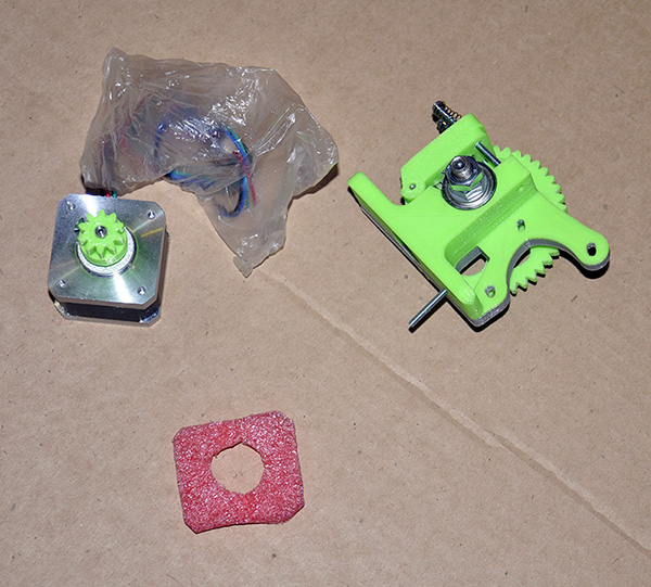
The gear that we are going to put on the motor. Do not overtighten it, as most likely you will have to move it forward-back later on.

Extruder body: I was experimenting with double extrusion, don't worry. Note the holes for nuts, you will most likely have to widen them in order for the nuts to fit.
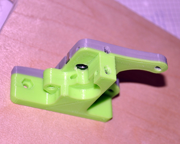
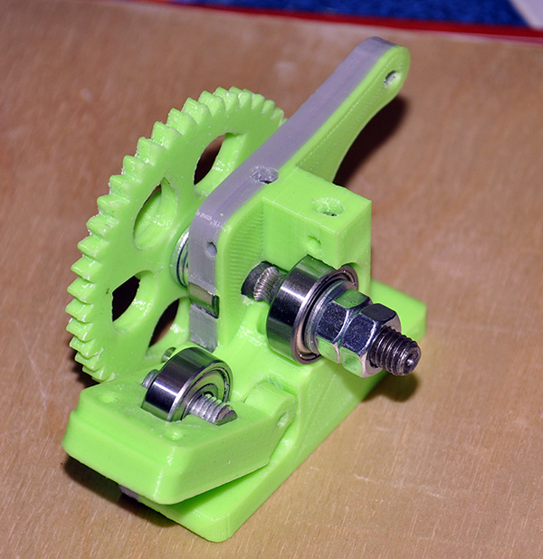
Install the bearing. This one supports the bolt, it has to fit tight and not to fall off by itself.
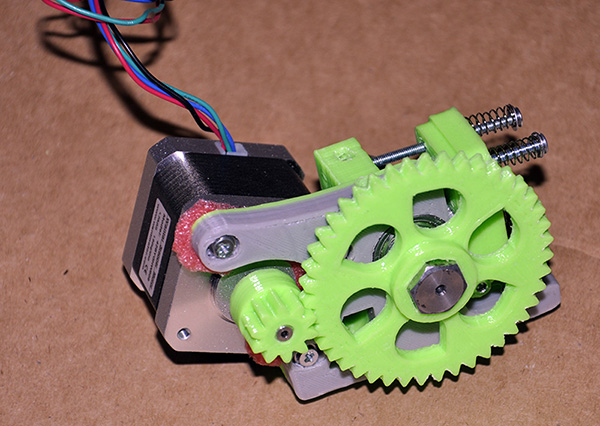
Bolt, large gear, a second bearing, nut and a lot of washers. We use washers to move the gear away from the extruder body.
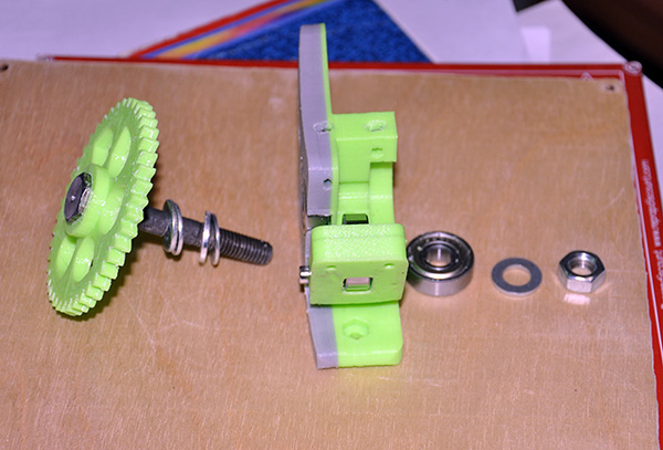
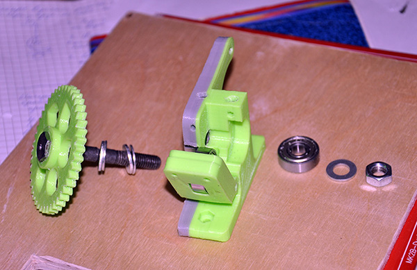
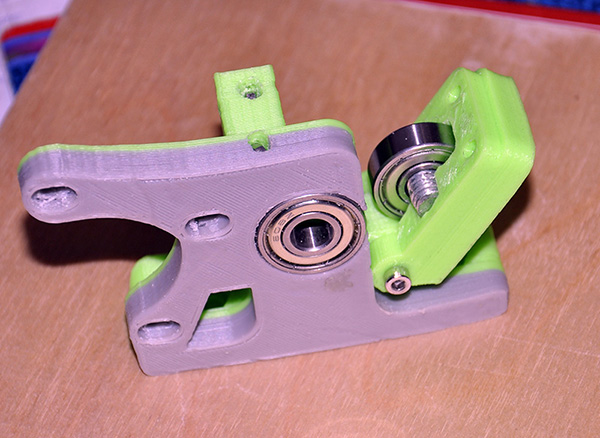
Assembled extruder (mechanics).
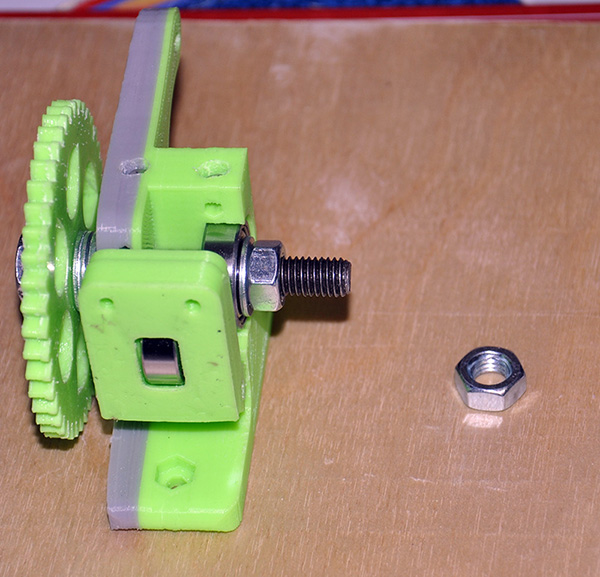
Then we add a second nut. See, we do not want to put a lot of force on the body of extruder, but in the same time, it moves, it vibrates: it has to be tight. So we put a second nut, and screw two nuts together, tight.
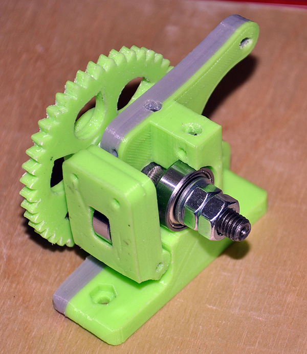
Note the hobbed bolt's working area and a bearing aligned, this is another reason we need extra washers. Also make sure you removed extra plastc preventing the bearing to reach the bolt. Use knife, file or like I did: use cutter.
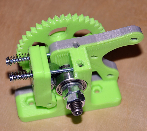
These bolts with springs are pressing the bearing against the bolt. Springs have to be as strong as you can get.
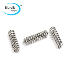
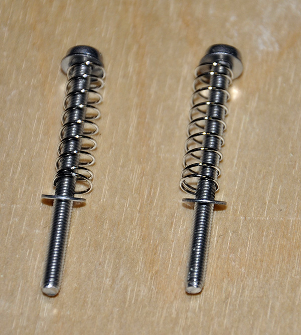
On the photo, bolts are tightened about half as strong as necessary.
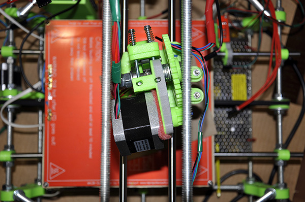
Installing the motor.
Next task is to install the motor. As one of the bolts that will hold extruger on X-axe is located under the motor's body, I put it there in advance., As I found later, it was not necessary, you can install / remove this bolt with the motor in place, using tweezers.
This motor vibrates stronger than Z-motors, accordingly, I am using a thick layer of a foamed plastic.

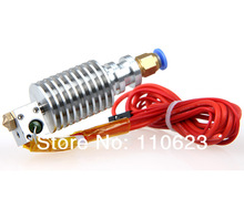
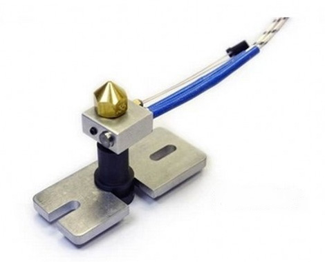
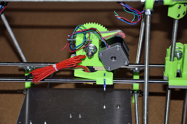
Installing extruder head.
Extruder head (hot end, J-Head) is installed on the detail, made of the plywood. See, extruder motor creates a lot of force, while extruder head produces a lot of heat. an we trust plastic in such situation?
The wooden part is made of the plywood 8-12 mm thick (measure the cold end of your extruder, it should fit tight).
This is what an aluminium analog looks like, you can purchase it on eBay or Ali. Frankly, I am not sure it is better than the plywood one, as wood conducts less heat, so less heat will be transfered to plastic.
Installing X-axe and extruder.
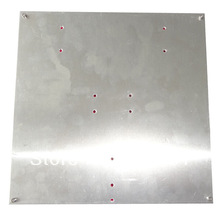
Aluminium plate, the base of a print bed.
This is not a part of an extruder :) but installing it after the extruder is not that convenient, so let's do it now.
The two plastic details you see on a photo will hold the belt (we are going to install it later) in place. Before the belt is installed, there is no pointto tighten them.
Keep in mind, that the print bed, even with the belt in place, moves when you tilt the printer. Control it by hand.
Installing the X-motor.
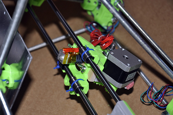
X-motor is installed using nuts, similarly to what we did with Z-motors; we use foamed plastic to reduce vibration.

Installing the extruder.
The base of an extruder (see next photo) is supposed to be screwed to the platform sliding by X-axe, using nuts. I made a slight change to the design, and never regretted it.
However, there is a problem. If you install an extruder the way it is shown on the photo, it might (give or take few millimeters) collide with the frame. This is what extra holes are, they allow us to rotate an extruder to a certain degree, to turn, so to speac, the fridge, so it can go through the door. If the angle of rotation is too big, drill extra holes between existing ones.
What we have to assure is a) extruder not colliding with frame, especially when X-axe is at its upper point (i2's working area is 20x20x10cm).
b) The large gear should not touch the belt. If it does, turn extruder, as I just described.

On the next photo, you can see extruder turned slightly.
Installing Y-axe and print bed.
Assembling the print bed.
Print bed is just a heated surface. We heat it in order to keep the plastic stuck to the surface, therefore, all we are interested in is the upper side of it. However, if we do nothing about it, the heat will be emitted from both upper and lower sides, which is counterproductive in terms of required power.
Heated bed:

To stop loosing heat, we insulate the print bed, attaching a sheet of plywood to its bottom side. We use 8+ mm plywood (do not meke it too thick, and is 1-2 mm wider than the heated surface you have. As heated surface can be anywhere between 20x20 and 22x22 cm, use the ruler. Also you can see that one side is cut - we are going to put wires there.
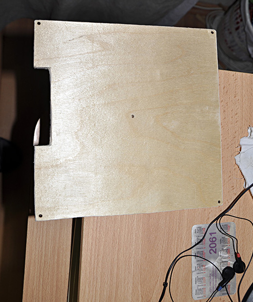
Carefully, measure distances and drill five holes, four for the bolts on holding th eplywood together with the heating surface, and one in the center, for termistor.

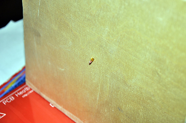
The termistor is supposed to go through the plywood and into the hole in the middle of a heating surface. Drilling here must be precise.
We are going to talk about electronic parts later, but the termistor is installed now.

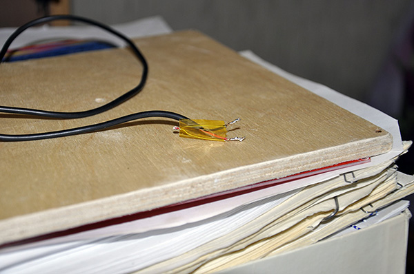
As usual, the spec does not say anything about the way termistor wires should b fixed. First I used adhesive tape, but it proved to be not reliable. Then (the tape is not required anymore, but I left it in palce) I used the plastic detail, similar to what we use on Z-axe. And finally - my know-how - I placed a fragment of a toothpicker into the termistor hole, which holds the wire in a firm and reliable way.
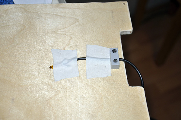
When soldering termistor's wires, make sure they do not touch each other. I used the tape.
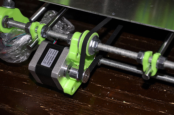
Installing Y-motor.
Take a piece of the belt and install the Y-motor.
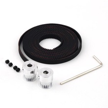
The belt should go under the plastic details, and it should be tight, both the belt and screws.
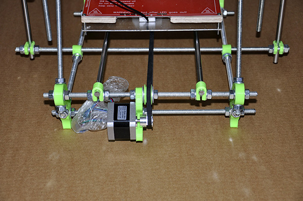
Finishing assembling.
Put together all three layers of a "sanwich" using long bolts with springs. The idea is to be able to screw / unscrew individual bolt, moving corners of a print bed up / down. We need the extruder head to remain on the same distance from the print bed, no mater where it moves by X and Y axes.

Electronic components.
First of all, you don't have to be an expert to select proper components. All you need to do is typing in aliexpress something like "reprap termistor", to find out what termistors to use.
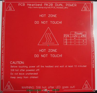
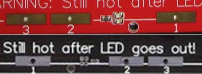
Soldering the print bed wires.
The theory can be found here. As you can see from pictures, I used MK2b Dual Power, one particular kind of the heating surfaces. If you have a different model, study the specs to learn the way to solder it. In my case, one wire goes to 2 and 3 (yes, we shortcircle them), and the second one goes to 1.
Wires are supposed to be attached underneath the heating surface, and they do not go through the holes: we are going to put the glass on top.
Here is (for my case only!) the guide, depending on what power source you use:
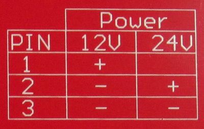
This is what contacts look like:
X, Y and Z stops.
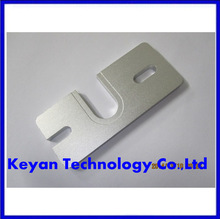
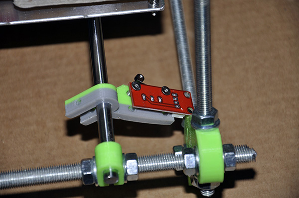
The most complicated one is an Y-stop. There is a flaw in a Prusa i2 design, the bolt of the print bed can collide with the bolt of the Y-stop. I have redesigned the stop, it is now twisted, so there is no collision: download.
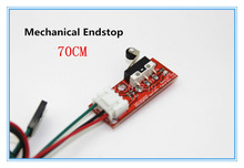
X-stop is installed on the smooth rod of an X-axe, it fires when extruder touches it. Z-stop is installed on the smooth rod of Z-axe.
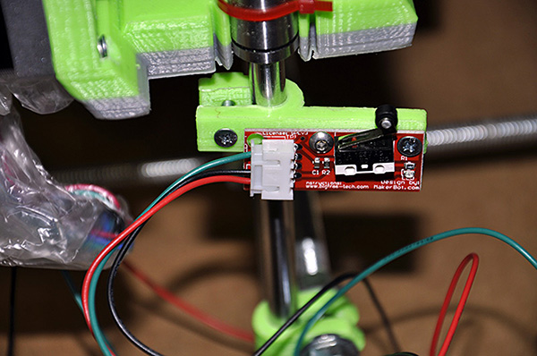
In a particular design, I chose to invert axes in order to make wiring easier. It is not against specs, and we are going to compensate for it in software settings below. If you look from the Y-motor's direction, Y-stop is on the far left side, X-stop in the right, and Z-stop at the left. Let me repeat, it is not against the spec, I chose this setup because I am planing to install Arduino on the close-left side.
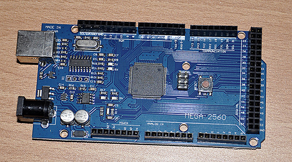
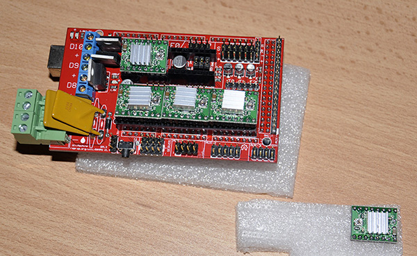
Arduino Mega.
There are many options in terms of the processor of our printer, some general purpose and some designed specifically for printing. I chose the legendary Arduino Mega. Yes, it is not specialized, so we have to add some componente instead of having them preinstalled. But if something burns out, you will not have to replace the whole board, also, Arduino has huge support outside the Reprap community, any question will be answered on forums.
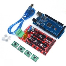
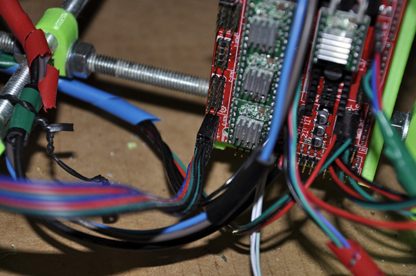
By itself, Arduino can not produce enough current for motors, so we are going to use RAMPS, in my case it is RAMPS 1.4. It is being installed on top of Arduino, and then motor shields (below) are installed on top of it.

Motor shields.
Shields coltrol motors, there are four of them alltogether: X, Y, Z (two motors use one shield) and an extruder. If the printer uses dual extruder, we add the fifth shield.
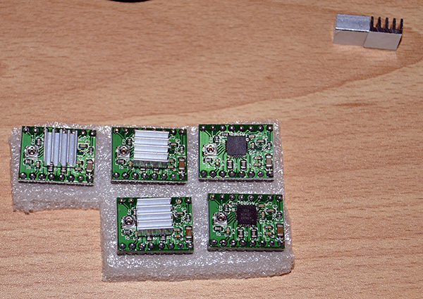
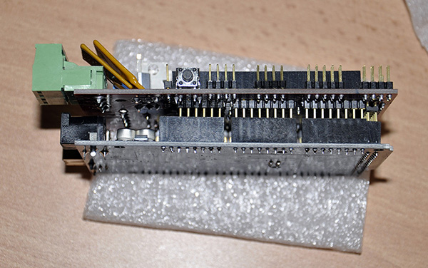
Important! On RAMPS you can see power jacks and yellow square details next to them. On motor shields you see a tiny screw - the head of a potensiometer. Now, this screw (usually refered as "pot") must be facing the direction, opposite to power jacks. If you put the shield wrong way, it will burn.
Wiring.
The following diagram shows the wiring from RAMPS to peripherial devices.

End stops.
As an example, I am going to use end stops, asuming that you can figure out the rest (motors and termistors). The diagram (above) is very straightforward after all.
As can be seen from a very straightforward diagram :) endstops are connected to a group of contacts on the upper right corner (of a diagram) in such a way, that we use every second pair: X-stop connected, skip the next pair, Y-stop connected etc.
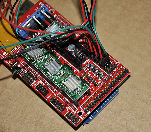
Attaching the power supply unit.
The next step is to provide the power to our assembly.
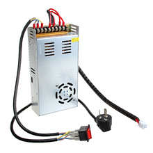
The power supply unit should provide 12 volts and about 300 watts, you can use computer power block or the one I used (see photo). Mine is more compact and fits under the printer. Now, if the PSU isn't powerful enough, there will be insufficient current, motors will skip steps and the hot bed will not be hot enough. As the result, your print will be ruined.
Voltage is low - 12 volts - nevertheless I expect you to know how to work with electricity. If not, please learn.
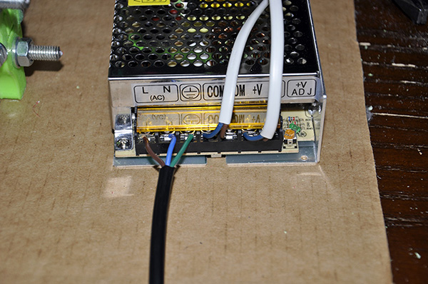
Anyway, four lines connected to PSU to RAMPS. RAMPS provide power to (see diagram) (see on photo, on the left) Heated Bed, Hot End and (not on a diagram) you can connect an extra fan to cool shields themselves.


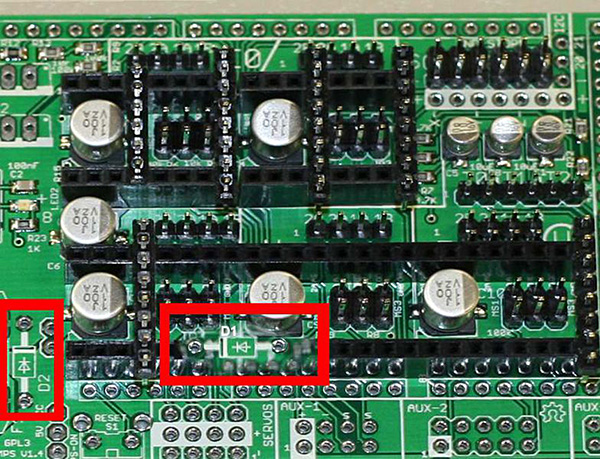
A logical question: where the Arduino itself gets its power? This is a rather complicated story, as (or should I say "as always"?) this is not part of specs. You can read some basics here. Briefly, we can get power from RAMPS and pass it to Arduino. To do it, we need to add two diodes (in theory, one might prove enough), then... Anyway, I almost bought those, fortunately, I found that my Arduino came with diodes already soldered in. See, what I bought was "Ардуино + RAMPS + shields" FOR REPRAP, so the seller took care of a potential problem.
It should be mntioned, however, that sometimes diodes are soldered in wrong way, sometimes (been there!) Arduino's voltage regulator breaks (because I placed the shield wrong way). So if your Arduino is damaged and refuses to use power via diodes, you still can get 12 volts (not higher!) from the PSU and send it to Arduino's barrel adaptor (the otherwise unused round jack). It should work.
Here you see places diodes should be soldered t:
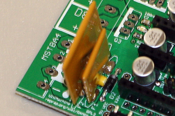
This is what the diod looks like, note the orientation (the strip on its body):
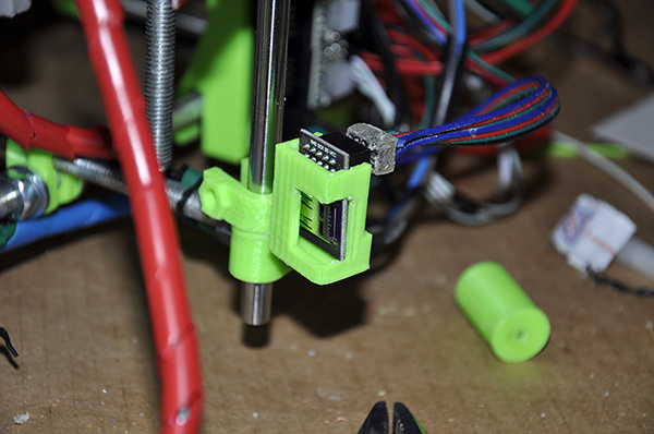
Connecting SD reader.
Reprap is capable of so-called "headless" printing, where "head" stands for a computer. Indeed, let's write commands to the SD card, and then read them using Arduino!
To use SD reader with Arduino, we use special shields:
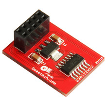
The only problem, it sticks on Arduino's side, which isn't estethically pleasing:
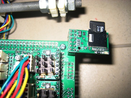
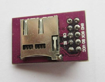
To fix the problem, I designed (download) an SD Holder, that allows to move the shield away from Arduino, and to place it under the Z-stop. Looks better:

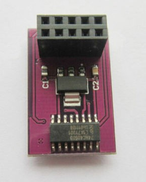
As you can see, I used a home made wire, instead, you can buy "SD card extender":
The shield itself is being held in a plastic holder:

To do headless printing, you need to: save a file containing G-codes on SD card's root, depending on the firmware (see below) it should be called init.g or auto0.g, then insert the SD card into the Reprap's reader, and then to turn on printer's power. Do not feel bad it nothing happens: it takes some time for the heated bed to reach the working temperature.
Installing Arduino and RAMPS.
As usual, specs say nothing about where on a frame to place the electronics. There are few solutions, by the number or Reprap's sides :)
My choice: if you look from the direction of Y-motor, Arduino is at the left-closest to you side of a frame. As you have probably guessed, the spec doesn't say anything about the way we attachthe Arduino_RAMPS+Shields to the frame. I have designed an Arduino Holder, simply speaking, a box holding our electronic components. Holder is fixed on a bottom rod (a horizontal one) and is tigthed up to a side one using plastc tightener.

Additionally, we can also place a fan holder, on a Z-axe, to cool down shields. My shields are not that hot somehow, so I chose to ignore that option.
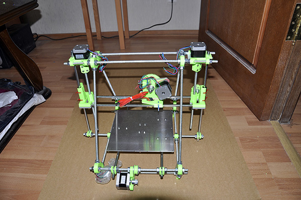
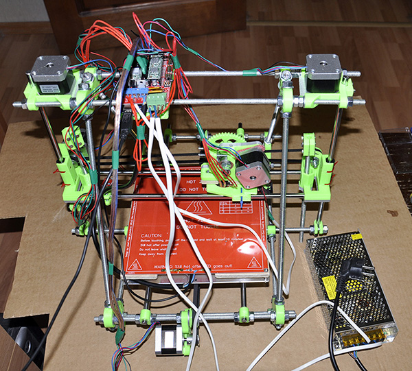
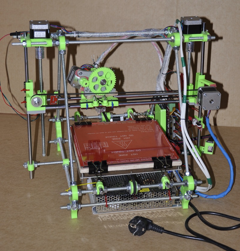
The look.
At this step, our printer looks kind of messy. Our task is to hide wires under some kind of shilding, to make it look neat. An industry standard is "PC neat", I use painting tape which is better:
Software.
There is nothing more discouraging, then to find ten incomplete guides instead of a single complete one. With all my respct to the opensource development model, the chaos here is unbelievable, compared maybe only with the mess in the commercial software development field.
So we are going to take a different way.
1. Download Arduino's software. This is surprisingly straightforward, just take it fromofficial site, follow the "download" link for your operational system. You have to install this software on your computer, in order to use it later to install so-called "firmware" on Arduino. I used this version.
2. Download Sprinter. This is a set of files which Arduino's soft (see 1) will turn into Arduino's firmware. If you need the last version, use Google, if you want the version I used, here it is. Note, that this is the version I modified for a specific printer (this one), so in theory, if you follow my steps, it will work "out of the box".
3. Connect Reprap to a computer using USB cable. It will either be recognized, or not. Go to Device Manager (I am talking about Windows here, if not, you are on your own, sorry), find our device. In Ports (COM & LPT), find our printer, or in "Other Devices" find an unrecognized "Unknown Device". Click on it with the right mouse button, choose "Update Driver Software" - "Browse my computer for Driver software". Select "arduino.inf", located in "Drivers" folder of Arduino Software (not in "FTDI USB Drivers" sub-folder). At this point, Windows should manbage.
4. Start arduino.exe (see. 1), open Sprinter.pde in Sprinter directory. It will open another copy of arduino.exe, you can now close the first copy. Don't ask :)
Press an arrow icon on a toolbar, the software will be compiled and sent to Arduino.
Important note: to do steps 1 - 4, you don't need PSU, USB connection will provide sufficient power to Arduino. Especially considering, that we haven't tested anything yet.
5. Copy Repetier Host to your computer. There are countless programs that can take STL file, turn it into G-codes and send it to 3d printer, I like Repetier. Lately they abandoned opensource model, and even began displaying commercials. Here is the last "fair" version: Repetier Host.
Start Repetier Host, turn on printer, in Repetier Host, click "Connect" on toolbar. Switch to the last tab (manual), and test motors, extruder and heaters, one by on. Be ready to unplug it on any sigh of an emergency, which is smell, shieds overheating (test shield's radiator with finger), loud (too loud) motors and when the motor does not stop atfter hitting the stop.
Test print.
Preparing an STL file sor a simple test (cube 2x2x1), and print it, first from Repetier, then from SD card. Do not forget about a glass covering a heated bed. A glass should be heat resistant borosilicate, ideally, sitall one, use "presentation clips" to press it against the heated surface (see printer's photo). Note that clips should not bump on anything as heated bed moves.
The plastic does not hold on glass well. You print - it falls off, before you finished. People use capton tape (search "reprap tape"), or hair spray. I use hair spray or sitall glass. Be careful, if your hair spray smells perfume, your house will smell too... strong.
On this link you can find a small (79 Mb) video of a printer (this one) printing SD holder for itself. Keep in mind, video was created before I wrapped all wires, so the printer looks messy.
Conclusion.
As I said. When making that printer, I wanted to learn... making printers... I am going to post my notes, as I want to build other models, too. Feel free to support me :)